This project is titled the design and construction of a water level sensor system. It is designed to indicate the level of water to over-head tank.
In this system, transistors are used; all the transistors are working as a switch. When the water touches the metal contact in which base of each transistor is connected, small current flows and turns on the transistor. When a transistor turns on, LED connected to it glows. Thus LEDs will be turned on depending up on the level of water.When the water is empty the wires in the tank are open circuited and the resistors pulls the switch low hence opening the switch and LEDs are OFF and vice-versa.
TABLE OF CONTENT
TITLE PAGE
APPROVAL PAGE
DEDICATION
ACKNOWLEDGEMENT
ABSTRACT
TABLE OF CONTENT
CHAPTER ONE
- INTRODUCTION
1.1 OBJECTIVE OF THE STUDY
1.2 SIGNIFICANCE OF THE STUDY
1.3 SCOPE OF THE STUDY
1.4 APPLICATION OF THE STUDY
1.5 LIMITATION OF THE STUDY
1.6 PROJECT ORGANIZATION
CHAPTER TWO
2.0 LITERATURE REVIEW
2.1 REVIEW OF DIFFERENT TYPES OF WATER SENSOR
CHAPTER THREE
3.0 CONSTRUCTIONS METHODOLOGY
3.1 CIRCUIT DIAGRAM
3.2 CIRCUIT DESCRIPTION
3.3 CIRCUIT OPERATION OF THE WATER INDICATOR
3.4 COMPONENTS USED
3.5 THE WORKING PRINCIPLE
3.5 POWER SUPPLY UNIT
3.6 POWER SUPPLY UNIT
3.7 SPECIFICATION AND OPERATION OF SYSTEM COMPONENT
CHAPTER FOUR
4.0 CONSTRUCTIONS
4.1 CIRCUIT OPERATION
4.2 CIRCUIT DIAGRAM
4.3 COMPONENTS REQUIREMENT
4.4 WORKING OF AUTOMATIC WATER LEVEL CONTROLLER
4.5 COMPONENTS PIN-OUT
4.6 POWER SUPPLY UNIT
4.7 POWER SUPPLY COMPONENTS
CHAPTER FIVE
5.0 RESULT ANALYSIS
5.1 INSTALLATION OF THE COMPLETE DESIGN
5.2 CONSTRUCTION PROCEDURE AND TESTING
5.3 CASING AND PACKAGING
5.4 ASSEMBLING OF SECTION
5.4 TESTING OF SYSTEM OPERATION
5.5 PROBLEMS ENCOUNTERED
5.6 COST ANALYSIS
5.7 DESCRIPTION OF COMPONENTS USED
CHAPTER SIX
6.1 CONCLUSION
6.2 RECOMMENDATION
6.3 BIBLIOGRAPHY
CHAPTER ONE
- INTRODUCTION
This work is titled design and construction of Water Level Indicator. It is best suited for overhead water tanks to display the amount of water. The circuit consisting of 4 LED’s used to indicate ¼, ½, ¾, full levels.
Nowadays everybody has overhead tank at their homes. But everyone who has a water tank above knows the kind of problems that they face. Firstly there is no system to track the water in the tank. Then there come a secondary problem that is when their water pump is started they have no idea when it gets filled up and sometimes there are situation where the pump keeps on pumping water to the tank and the water startsspilling out from the tank. There is wastage of energy as well as wastage of water.
Basically the unit is made up of various sensors acting as a switch. Let me explain in a simple way. What happens is when you turn on you water pump, the water starts to get pumped from your underground reservoir or from your underground water supply from the pipes to your water tank. In the tank there is a set of sensors ( to be precise there are 4 sensors), in the water tank. Just think them as a switch, as the work of the sensor will be to connect a circuit. I will explain in details in my instructables. So the water starts to get filled in the tank and when the water level in the tank starts to rise up, what happens is that the sensors that is installed in the tank starts to get activated one by one indicating the water level in the tank. And finally when it reaches to its top most sensor, there will be a visual display as well as a sound from the unit indicating that the water has filled in the tank and one can be alerted that the tank has been filled up and the water pump has to be switched off saving the electricity bill as well as over flow of water from the tank.
There are Four parts in this project:-
(i) The Sensor Part
It is generally a fixed support inside the tank having some nuts and bolt with wires coming out.
(ii) The Circuit Part
It comprises the brain of the module, where in all the various inputs from the sensors are fed. It is the unit from where you will get all the information of how much of water is in the tank.
(iii) The Power Supply
It is the part where in you will be converting the A/C voltage to a regulated voltage of 12V to the Circuit.
(IV) The Buzzer Part
It is responsible for bringing up the sound when the water level fills up in the tank. It will also be having a speaker or a buzzer to alert.
1.2 OBJECTIVE OF THE STUDY
- To institutionalize social regulations level that govern the allocation, use and management of water for the different purposes.
- To achieve equitable and sustainable access to groundwater to all farmers through sharing of resources and socially regulated demand management of the resource.
- To achieve equitable and secure access to water for drinking, sanitation and domestic needs at affordable costs for all households or company within the project area and project period.
- To construct an electronic device that can automatically detect water level (high and low) with high precision.
- To control the supply of water.
1.3 SIGNIFICANCE OF THE STUDY
Significance of water level is as follows:
- Suitability: These water level controllers are ideally suited for normal water as well as for ultra low conductivity water with less than 1 micro/moh.
- Easy to Operate: this system come fitted with sensitivity setting which can be provided externally on a dial or with internal settings.
- Settings: It is equipped with technology which works on low or high sensitivity settings on the same machine and thereby saves costs of buying and using two different machines.
- Materials of Construction: this water indicator system is protected the against corrosion.
- Safety: This system is highly insulated, leakage proof and works without creating any noise.
- Save roofs
- Save water
- Save electricity
1.4 SCOPE OF THE PROJECT
This system provides you the flexibility to decide for yourself the water levels for operations of pump set in upper/lower tanks. |
Built in Indications for showing Full, Empty Levels in Upper Tank and Lower Tank Empty Indication. |
Manual operation switch for special operations like watering the plants from pump set. |
The system ensures no overflows or dry running of pump there by saves electricity and water. |
Consume very little energy, ideal for continuous operation. |
1.5 APPLICATION OF THE PROJECT
Water level indicator is an application which detects the level water then triggers the pump and blows alarm and vice versa. They are useful devices and play an important role in various industries such as automobile, irrigation, and also at homes, or wherever water is pump either underground or overhead.
1.6 LIMITATION OF THE PROJECT
Sensors used are built with conductive material, which means that they are subject to rusting or corrosion. When rusting occur the sensors will stop conducting thereby causing this device will stop working.
1.6 PROJECT WORK ORGANISATION
The various stages involved in the development of this project have been properly put into five chapters to enhance comprehensive and concise reading. In this project thesis, the project is organized sequentially as follows:
Chapter one of this works is on the introduction to water level indicator. In this chapter, the background, significance, objective limitation and problem of water level indicator were discussed.
Chapter two is on literature review of water level indicator. In this chapter, all the literature pertaining to this work was reviewed.
Chapter three is on design methodology. In this chapter all the method involved during the design and construction were discussed.
Chapter four is on testing analysis. All testing that result accurate functionality was analyzed.
Chapter five is on conclusion, recommendation and references.
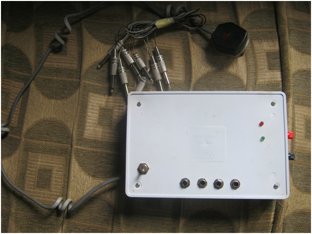
OUR DESIGN PICS
Below is the design pic for the related project, and click fb.me/hyclas for more of our project design pics:
RELATED TOPICS/MATERIAL
1]. DESIGN AND CONSTRUCTION OF A WATER LEVEL INDICATOR
2]. DESIGN AND CONSTRUCTION OF A MICROCONTROLLER BASED WATER LEVEL CONTROLLER USING 89C52
3]. DESIGN AND CONSTRUCTION OF A WATER LEVEL INDICATOR WITH SINGLE 7 SEGMENT LED DISPLAY
4]. DESIGN AND CONSTRUCTION OF A RAIN OPERATED WIPER
5]. DESIGN AND CONSTRUCTION OF A RAIN DETECTOR (ALARM)
6]. DESIGN AND CONSTRUCTION OF A DARK ACTIVATED ALARM
7]. DESIGN AND CONSTRUCTION OF LIGHT SENSITIVE ALARM
8]. THE DESIGN AND CONSTRUCTION OF AUTOMATIC FENCE LIGHT CONTROLLER
This material is a complete and well researched project material strictly for academic purposes, which has been approved by different Lecturers from different higher institutions. We make abstract and chapter one visible for everyone.
All Project Topics on this site have complete 5(five) Chapters . Each Project Material include: Abstract + Introduction + etc + Literature Review + methodology + etc + Conclusion + Recommendation + References/Bibliography.
To "DOWNLOAD" the complete material on this particular topic above click "HERE"
To view other related topics click HERE
To "SUMMIT" new topic(s) OR you did not see your topic on our site but want to confirm the availiability of your topic click HERE
Do you want us to research for your new topic? if yes, click "HERE"
For more information call us on:+2348146561114 (MTN) or +2347015391124 (AIRTEL)
You can also visit our facebook Page at fb.me/hyclas to view more our related construction (or design) pics
IF YOU ARE SATISFIED WITH OUR SERVICES, PLEASE DO NOT FORGET TO INVITE YOUR FRIENDS AND COURSEMATES TO OUR PAGE.